

What Is a Linear Actuator, and How Does a Linear Actuator Work?
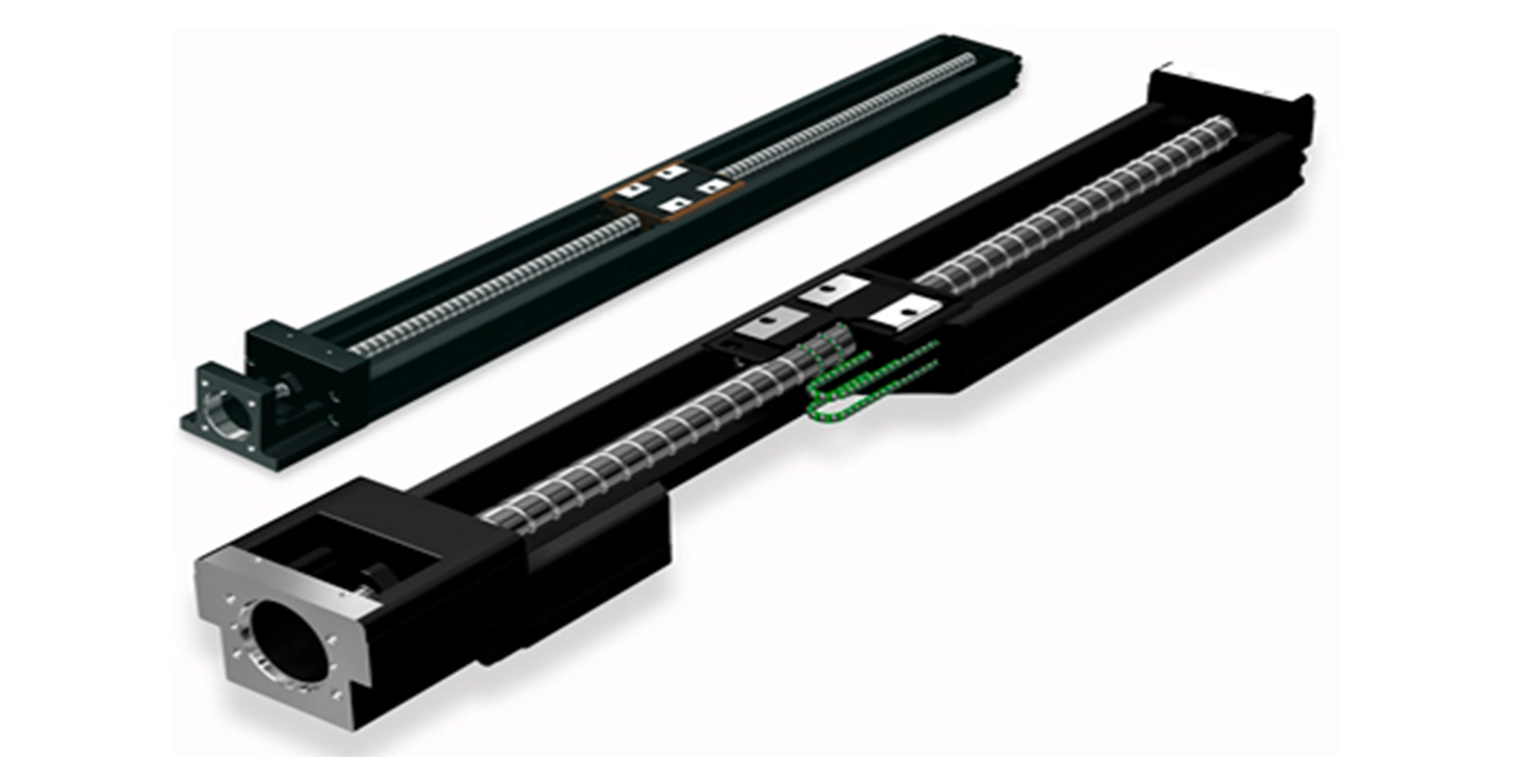
A linear actuator converts the rotary motion of an electric motor into straight-line push or pull force. Inside, a motor drives a gearbox, the gearbox turns a screw, and the screw's rotation is converted into the linear travel of a rod or carriage. That's the mechanism in one sentence, but the specific screw technology used inside the actuator changes its performance more than almost any other design choice.
size runs at only 20 to 40%, according to comparative data published by Tolomatic and Rockford Ball Screw. That difference determines how much motor torque is needed to produce the same force, how much heat the actuator generates, and how long it can run before it needs to rest.
Discover our range of linear actuators here (opens new window)
How the Core Mechanism Works
When power is applied, the electric motor rotates and drives the internal gearbox. The gearbox transmits torque to the screw, and the screw's rotation converts into linear travel of the rod or nut, extending or retracting depending on the motor's direction.
The gearbox is also where the actuator's speed and force characteristics get set. Since the motor's maximum available torque is fixed, changing the gearbox ratio is what lets the same motor produce either higher force at lower speed, or higher speed at lower force, which is why actuators in the same physical range are often available with very different performance specs.
Extension typically continues until a limit switch cuts power at the desired point, or a controller commands a stop based on position feedback. Reversing the motor's polarity then drives the rod back, retracting until the next stop signal. For a fuller explanation of what a linear actuator is and where it fits in a machine, see our guide to what is a linear actuator
What's Inside an Electric Linear Actuator?
A typical thrust-style electric linear actuator is built from a consistent set of components: an electric motor and gearbox at one end, a screw (lead screw, ball screw or roller screw) running through the body, a nut that travels along the screw, an inner push tube connected to that nut, and an outer protective tube that the inner tube extends from. Front and rear mounting attachments connect the actuator to the machine, and a sealing system protects the internals from contamination.
Many actuators also include internal limit switches to control stroke length automatically, stopping the rod at its programmed extension and retraction points without needing external sensors.
Ball Screw vs Lead Screw vs Belt Drive: Efficiency Compared
The screw (or belt) inside an actuator is the single biggest factor in how it performs, and the differences are measurable rather than marginal.
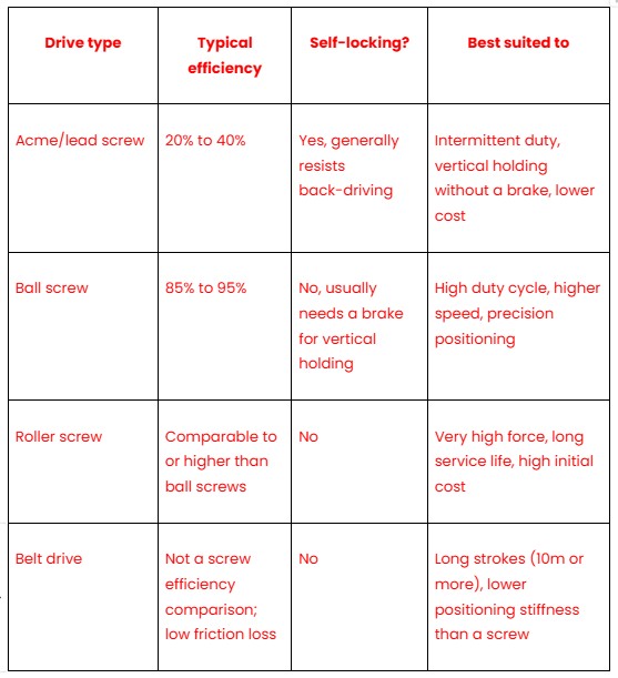
The lead screw's lower efficiency comes from sliding friction between the nut and screw threads, rather than the rolling contact a ball screw's recirculating ball bearings provide. That same friction is what allows an Acme screw to hold a static load without back-driving when power is removed, whereas a ball screw's low friction, the source of its efficiency advantage, generally means it needs a separate mechanical or electromagnetic brake to do the same job safely.
How Positioning Linear Actuators Work
Positioning linear actuators serve a different purpose from thrust-style rod actuators: precise, controlled movement of an object or subsystem within a larger machine, rather than a simple push or pull. Traditionally, this required a pair of profile rail guides mounted separately from the drive mechanism, set up to tight parallelism and height tolerances, a time-consuming and costly build.
A positioning actuator combines guidance, drive and a mounting interface in a single unit, so installation time and the risk of misalignment are both reduced. Drive typically comes from a ball screw for shorter, high-accuracy strokes, or a toothed belt for longer strokes where the additional cost of a long ball screw becomes impractical. For very high accuracy and running performance, some positioning actuators use rigid guide channels rather than separate rail assemblies, simplifying support along the length of the stroke.
How Are Linear Actuators Controlled?
Control complexity scales with the application. At the simplest end, a motor, power supply and switch are enough. More commonly, a servo or stepper motor is paired with a dedicated drive and controller, giving closed-loop control over position, speed and force. In larger installations, actuators are often controlled directly by a machine's PLC, while others run as semi-independent systems that still interface with a PLC for coordination, or accept complex, pre-programmed movement profiles from PC software rather than PLC logic at all.
Duty Cycle: Why an Actuator Can't Run Forever
Every electric motor generates heat when it runs, through resistive losses in its windings, and if that heat builds up faster than the motor can dissipate it, the motor overheats and fails. Duty cycle is the manufacturer's rated limit on how long an actuator can run before it needs to rest, expressed as run time divided by total cycle time.
A 25% duty cycle means an actuator running for 15 seconds needs roughly 45 seconds of rest before the next cycle, a 1:3 ratio of running to resting time. Standard electric linear actuators are typically rated between 10% and 25% duty cycle at their maximum rated load; running one continuously well beyond its rating is one of the more common causes of premature actuator failure, since duty cycle is a thermal limit rather than a soft recommendation.
Frequently Asked Questions
How does a linear actuator convert rotary motion into linear motion?
A motor drives a gearbox, which transmits torque to a screw running through the actuator body. As the screw rotates, a nut threaded onto it, or the screw itself, translates that rotation into straight-line movement of a rod or carriage, extending or retracting depending on the direction of rotation.
What is the difference between a ball screw and a lead screw actuator?
A lead screw (Acme) actuator relies on sliding friction between the nut and screw threads, giving roughly 20 to 40% mechanical efficiency but making the actuator self-locking against back-driving. A ball screw actuator uses recirculating ball bearings between the nut and screw, reducing friction and reaching roughly 85 to 95% efficiency, at the cost of needing a separate brake to hold a load when the actuator loses power.
Why are some linear actuators self-locking and others not?
Self-locking depends on the friction between the screw and nut. A lead screw's higher friction, the same friction that lowers its efficiency, prevents an external load from driving the screw backward when the motor isn't powered. A ball screw's low-friction rolling contact removes that resistance, which improves efficiency but means the actuator generally can't hold a vertical load safely without an additional brake.
What is duty cycle, and why does it limit how long an actuator can run?
Duty cycle is the ratio of an actuator's run time to its total cycle time, expressed as a percentage, and it exists because the motor generates heat proportional to how hard and how long it runs. Standard electric linear actuators are typically rated between 10% and 25% duty cycle; exceeding that rating for extended periods causes the motor to overheat, which shortens its life or causes outright failure.
How are linear actuators controlled?
Control ranges from a basic motor, power supply and switch for simple on-off applications, through servo or stepper motors with a dedicated drive and controller for closed-loop position control, up to full integration with a machine's PLC or PC-based software for complex, pre-programmed motion profiles.